


Back in 2018 I added some cooling fans to the back of our Thetford fridge on our Lunar caravan. The idea was to help it work better in hot weather. The cooling fans worked well and in the very last holiday in our Lunar, I shared how it was working, and it really did do an excellent job at keeping the fridge working perfectly, the issue was the installation was a bit of a bodge.
In between that original video, and this article we changed caravans. Our Bailey now has a Dometic fridge and I want to be able to add some cooling to the fridge to help it in the warmer months.
There were a number of issues with my original design, and in this iteration – I will be addressing these specific points:
1. I want a permeant solution, no dangling of cables
2. A safe installation, no chance of fingers getting caught.
3. A system that can automatically switch on when its needed
4. A system that can react to hotter conditions.
I came up with a suitable design for the MK2 that addressed all these points and I also came across the official Dometic kit, to add extra cooling. In a good way, my design was very similar to the official kit, but at a fraction of the cost and with a few huge improvements.
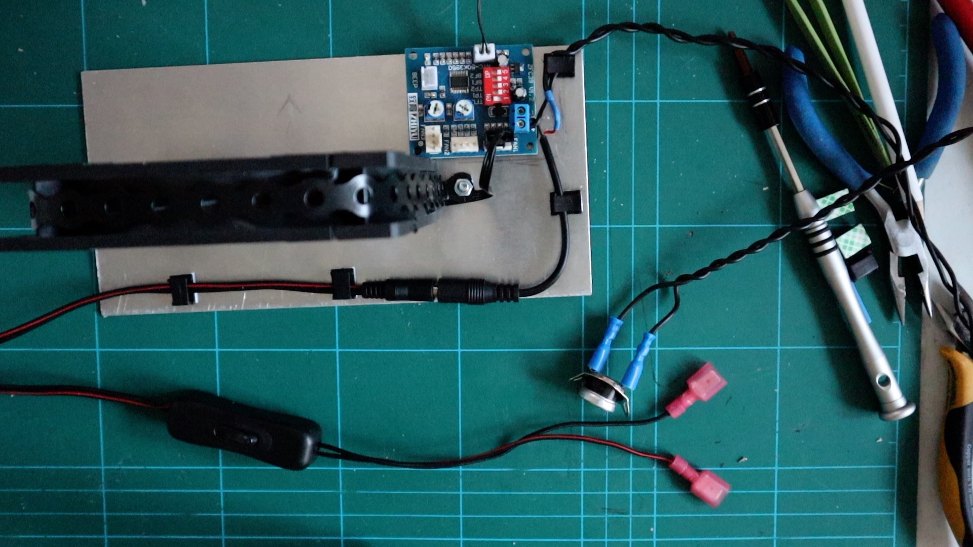
The Mk2 version is mounted on an aluminium plate and not the vents, and that’s because instead of sucking air in from the bottom vent or blowing out of the top vent, this will mount beneath the cooling veins on the back of the fridge and create a far more effective air flow.
The design
So, here is the design of my new system, and at the bottom of the article I have listed a shopping list.

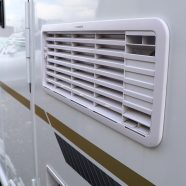
 I’ve mounted the 120mm fan to some aluminium and it measures 200mm x 100mm. its 1.5mm thick and will be mounted to the back of the fridge using very strong double-sided tape, the size of the aluminium is not important but I want a large surface area to hold the fan in place. I’ve drilled 2 holes at 150mm apart to mount the fan. The fan is mounted to the aluminium plate with a metal strip and secured with 2x M4 countersunk bolts.
This design has a fan controller to vary the speed depending how hot it is. The fan controller is mounted in the top corner, it’s fitted here to get the thermocouple as close to the cooling veins on the fridge as possible. This is affixed to the aluminium using some thick double-sided number plate tape. (For more info on this controller, click here)
The thermal switch is soldered in-line with the controller. I’m using heat shrink here to isolate the solder joints, however if you don’t have a soldering iron, all this can be completed using choc-block or crimp connectors.
The Installation
There are 3 things to install here, the fan assembly, the thermal switch and then finally the wiring. To begin with let’s fit the fan assembly.
The Fan
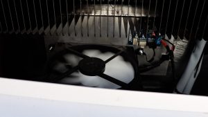
 Getting the fan assembly into position is a bit of a juggling act, But, rotating it and moving it behind the cooling veins the fan fits snuggly in. Its best to have a test run with the adhesive tape covered so you can fine tune the path the fan needs to take. Once stuck in position, you will notice how the fan is mounted below the lip of the to vent, which means it will drag its air in from the bottom vent, complimenting the thermal design of the fridge.
Thermal Switch
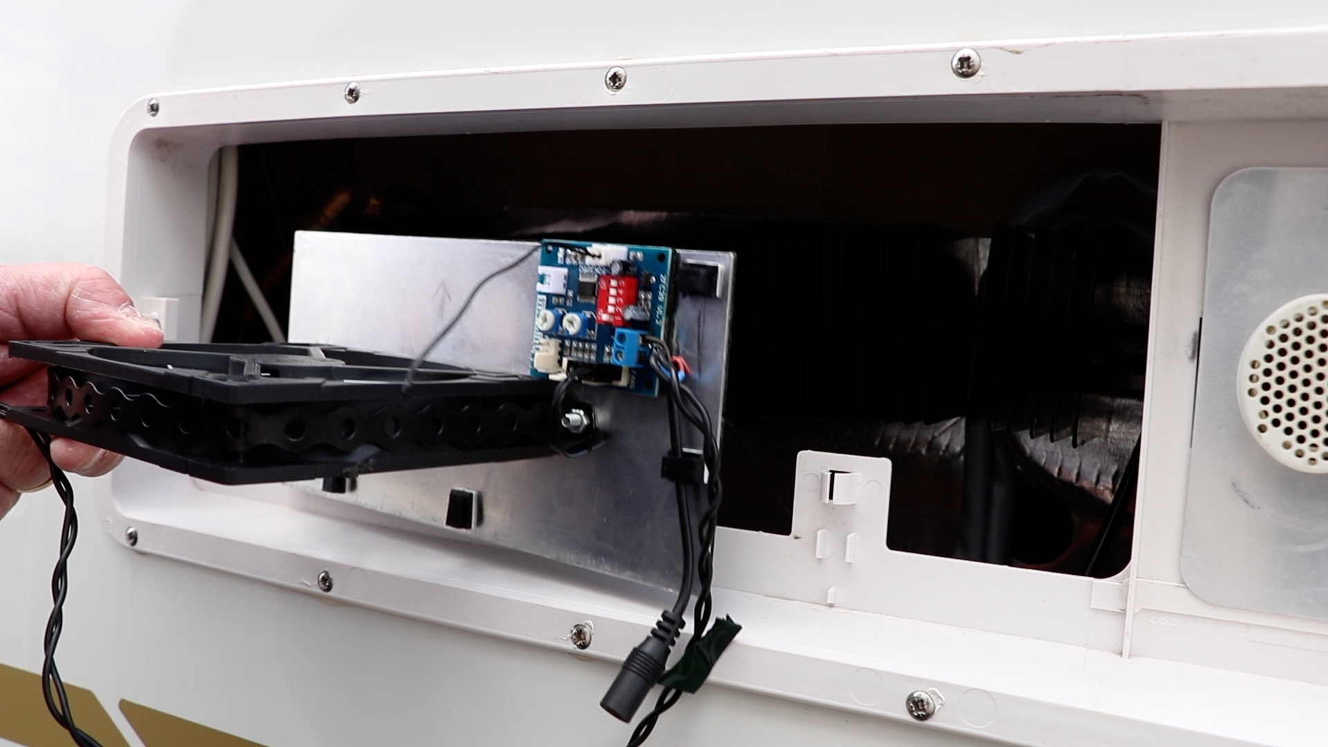
 Fitting the thermal switch is easy, we will attach this to the rear of the Fridge between the gaps of the finned pipe work. The gap is just big enough to fit, with some minor modification of our switch. If your Dometic Fridge is a different design, don’t worry – search for the installation instructions of the official kit, that will give you an idea on where to place the thermal switch. I’ve modified the switch by bending the wings, this makes it easier to fit around the pipe. I’m securing the switch in place with 2 cable ties, around the pipework and switch. The wires then run down and straight into the controller.
Wiring
 Unlike my 1st version where I ran a cable out of the kitchen window, I need a suitable power source behind the Fridge to make a permanent installation. Thankfully, there is a fused 12volt supply that is supplying the Fridge light and, on my Bailey, also supplies the 12volt permanent supply to the radio.
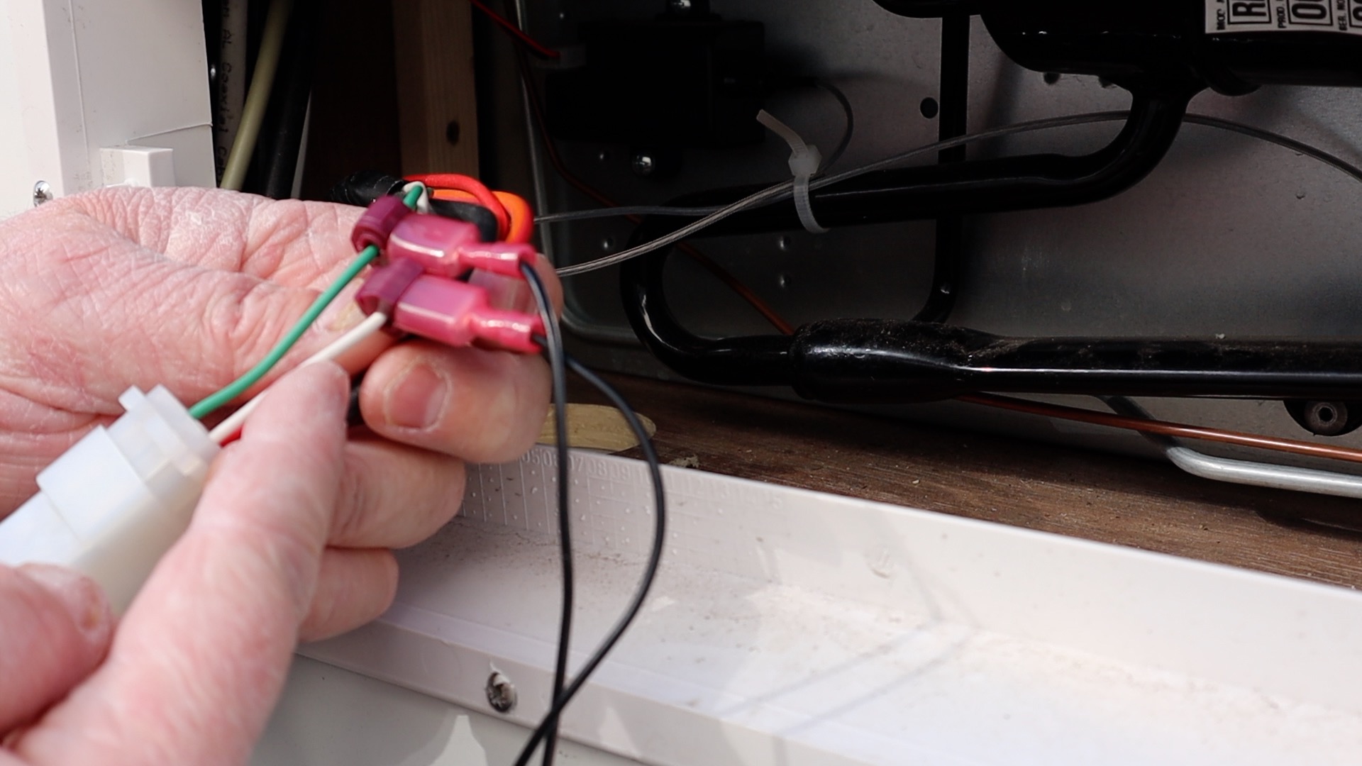
To tap into the 12volt supply I’m using scotch connectors. They splice into the cable, and allow me to add a spade terminal. It’s a great solution and if I need to, I can remove the spade terminals in the future.
In this instance the green wire is the +12v, the White is the ground. The connectors simply squeeze onto the cable and make a suitable ‘T” connection.
On some wire, I’ve connected the main switch, which I have cable tied onto the various cables at the bottom of the Fridge. From here I run the cable up to the top vent along with the other cabling that is already in place. I’ve cable tied my new wire in place to make them neat and out of the way.
Now that everything is installed, we need to test it. To make sure the fan spins and the controller works, to test with the fridge off, simply unplug the connectors to the thermal switch and add a wire between the 2 connectors, to allow current to flow. Once tested the vent covers are replaced and there is a noticeable air flow, some suction from the bottom vent but there is quite some output from the top vent.
The installation is quite easy. In total this would take no more than 30 minutes with all the parts gathered together. The trickiest part is making sure the aluminium is inserted without the tape sticking to anything you don’t want it to.
Shopping List
Fan https://amzn.to/36FDfcF
Controller https://amzn.to/2ZJ3pKa
Switch https://amzn.to/2zwn99f
Thermal switch https://trudg.uk/52dbb
wire 5m https://trudg.uk/vrx
crimps https://trudg.uk/dpo
T crimps https://trudg.uk/cjr
heat shrink https://trudg.uk/ebf
Aluminum https://trudg.uk/zxw
M4 bolts https://trudg.uk/za5
strap https://trudg.uk/rgy
Cable ties https://trudg.uk/3qz
Number plate tape https://trudg.uk/ho8
You will need minimal tools to complete this. If you want to solder the cables for the thermal switch, that’s fine however if you are using crimp connections already, simply use a spade terminal. So, in fact all you need is a terminal crimper, a sharp knife, a small screwdriver and a pair of cutters. Have a look at our list of tools on our Amazon StoreFront for some guidance.


Hi Dan
Finally got all the components to put together the fan project I have looked at the video on YouTube looking at the controller the dip switch setting is no1 up position and the rest down position? You did say check out the link to your other channel in the description but I couldn’t find the link? Biting at the bit to fit it I went to the caravan Wednesday 17th in Shropshire changed the solar controller to a Victron even though the caravan is a Coachman 2020 and not been used yet they only fit a basic controllers
Hi David, here is the link for the video.
https://www.youtube.com/watch?v=cRnuiG69OI4
The DIP settings are quite easy, keep 1 ON the rest off. No doubt, i’ll need to revisit this in the future. Good luck, and let me know how you get on.
Take care
Dan
The have a lunar delta Ri from 2018 running an 8 series dometic full size fridge. It’s performance in any kind of hot weather is dreadful but in particular when the awning is on as the fridge is on that side. In the hot weather at the start of August the fridge was running at 12 degrees at an ambient temp in the awning of about 30. I’ve watched all the videos and am going to try a hybrid of your Mk 1 and Mk 2 fridge fan. The official dometic paperwork suggests a fan location half way up the fridge which would be inaccessible for me and involve an expensive trip to the dealer. I’m therefore going to run three fans off the fan controller near to the upper vent as per your mk 1 project. I figure better to start with too much venting rather than too little. Incidentally there is a version 2 of the fan controller which allows you (by shorting part of the PCB) to run three fans to the separate connectors and they all get thermally controlled rather than fan 2 and 3 being on pots. However, if you opt for PWM PST fans they can be daisy chained to one connector on the PCB anyway. Hoping this improves the performance of my fridge….it can’t get any worse
Hi Dan,
Great video and information on parts used etc.
I’m just curious to see if you thought the controller temperature was higher than you’d like at 30 degrees and if there was a better controller? I guess the same system could be installed without the controller like the official kits do, so do you think your speed controlled version is better if it doesn’t kick in until 30 degrees?
Keep up the good work!
Dave
Hi, any update now used had a chance to use it? Sitting here with a fridge that’s not that cold and it’s not really warm outside thinking I need to sort this once and for all!
Hi Dan just seen your video and found the page, looking at the controller pcr this comes with a basic thermo sensor, can I ask the reason for using the always open sensor?
Many thanks
Wayne
Hi Wayne, the ThermoCouple on the PCB is used to ramp the speed up of the fan based on temperature. The Thermal Switch is used to activate this PCB. I dont want the fan running all the time, only when the fridge is hot – so the Thermal switch, only switches on when the fridge is running hot.
Hope that helps.